Gm Floor Dimmer Switch Wiring Diagram

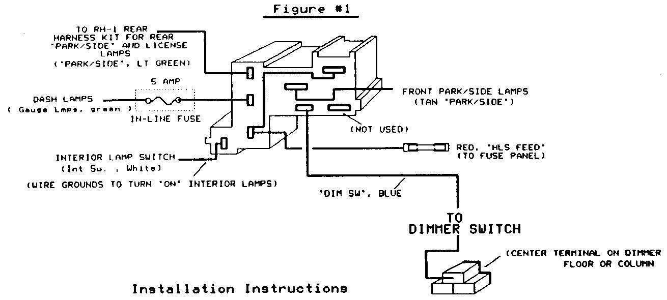
11125 Installation Instructions For Gm Style Dimmer Switch

How To Wire A Floor Mounted Dimmer Switch Great For Led Light Switching Youtube
Light Switch Wiring Diagram On 59 The 1947 Present Chevrolet Gmc Truck Message Board Network

Headlight Dimmer Switch Wiring Diagram Chevy Headlight Switch Wiring Diagram Free Wiring Diagram Cabtivist

Eb Headlight Switch Wiring Diagram Electrical Diagram Jeep Cherokee Headlights Headlights

Fy 1884 Floor Dimmer Switch Wiring Diagram Schematic Wiring
The dimmer switch plug will fit a floor mounted dimmer or gm column mounted dimmer.
Gm floor dimmer switch wiring diagram.
Oldsmobile Headlight Switch Wiring Diagram 02 Gmc Yukon Wire Diagrams Viiintagex Begaya Decorresine It
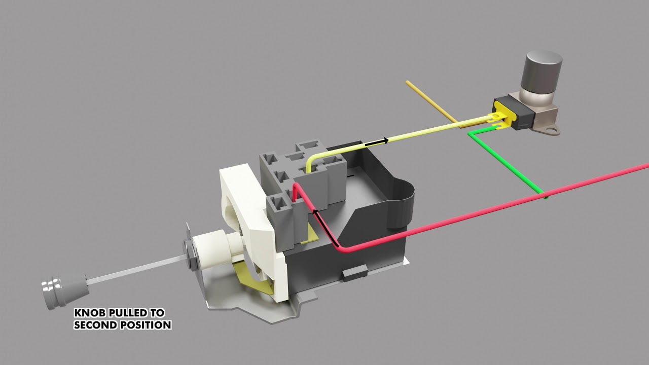
Gm Style Headlight Switch Youtube

Kd 0556 Highbeam Switch Wiring Diagram Download Diagram
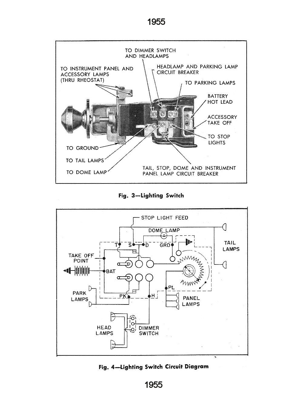
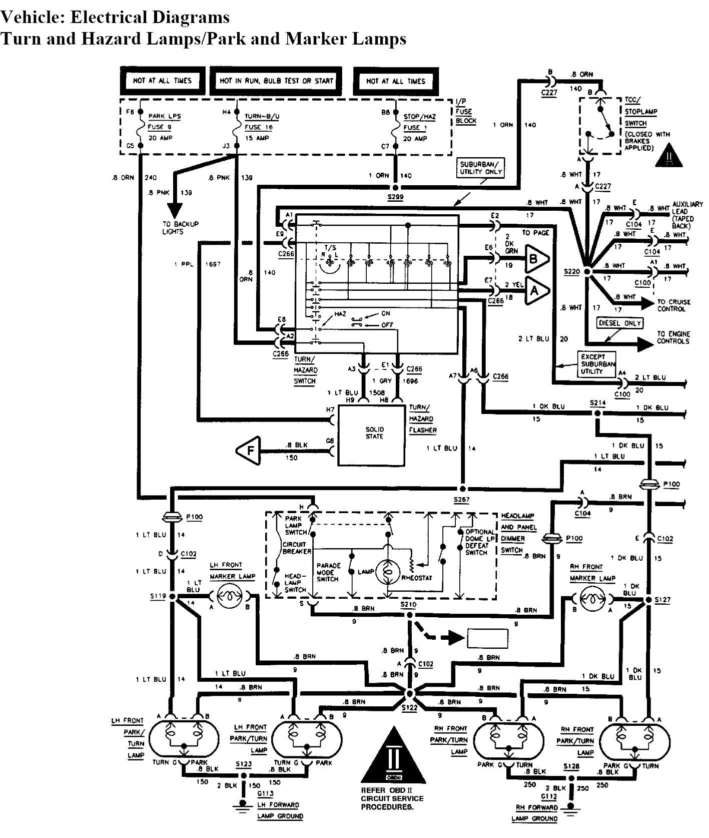
Chevy Wiring Diagrams
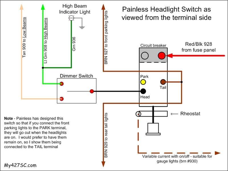
Diagram Chevy Truck Dimmer Switch Wiring Diagram Full Version Hd Quality Wiring Diagram Sbs1fuse6284 Lidiachambre It

I Need A Complete And Correct Wiring Schematic For The Dome Courtesy Light Circuit In A 1997 Gmc Yukon

Universal Ignition Switch Wiring Diagram Inspirational 1955 Chevy Of For 1955 Chevy Ignition Switch Wiring Light Switch Wiring Diagram Electrical Switch Wiring
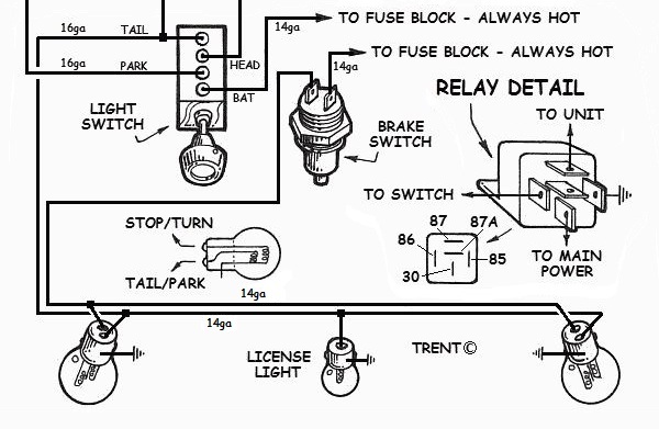
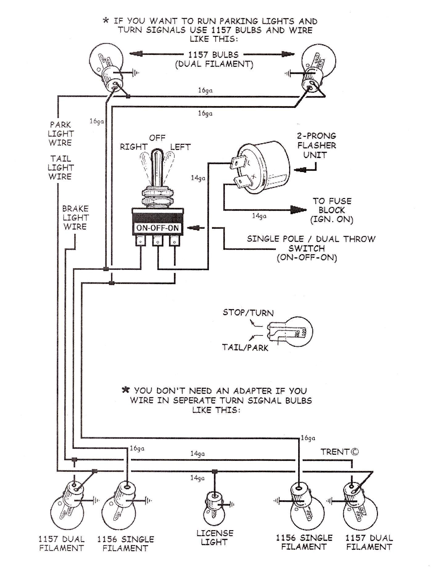
How To Wire Up Lights In Your Hotrod

Unique Dimmer Switch Wiring Diagram Manual Diagram Diagramtemplate Diagramsample Ingenieria Electronica Ingenieria Honda Wave

320 Headlight Relays 320 Ratsun Forums

Wiring Diagram 3 Way Switch Beautiful Electrical Timer Switch Wiring Diagram Light Switch Wiring Light Switch Electrical Wiring Diagram

Image Result For Drl Wiring Schematics 03 Silverado Diagram Alternator Silverado Headlights

67 72 Chevy Wiring Diagram 72 Chevy Truck Chevy S10 Chevy Trucks

Diagram Leviton 3 Way Switch Wiring Diagram Decora Wiring Diagram Full Version Hd Quality Wiring Diagram Thefactoryhka Gruppe Freiburg 1 De
Ididit Faq

Mgb Wiring Diagram Di 2020

Electrical Wiring Headlights Jack With A Light Switch Wiring 97 Similar Diagra Jack With A Light Switch Wiring Headlights Light Switch Wiring Dimmer Switch

Need A Wiring Diagram For 1992 Chevy 1500 Pickuptruck Chevy 1500 Chevy Chevy Silverado
3

New Wiring Diagram Immersion Heater Switch Electrical Wiring Diagram Trailer Wiring Diagram Diagram

Part 1 C10 Wiring Repair Universal Wiring Harness Youtube Alternator Diagram Electrical Wiring Diagram
1992 Chevy Truck Ke Light Switch Wiring Diagram 1997 Club Car Ds Wiring Diagram Mazda3 Sp23 Ab12 Jeanjaures37 Fr

12 1988 Chevy Truck Wiring Diagram Truck Diagram Wiringg Net In 2020 Electrical Diagram Electrical Wiring Diagram Chevy 1500
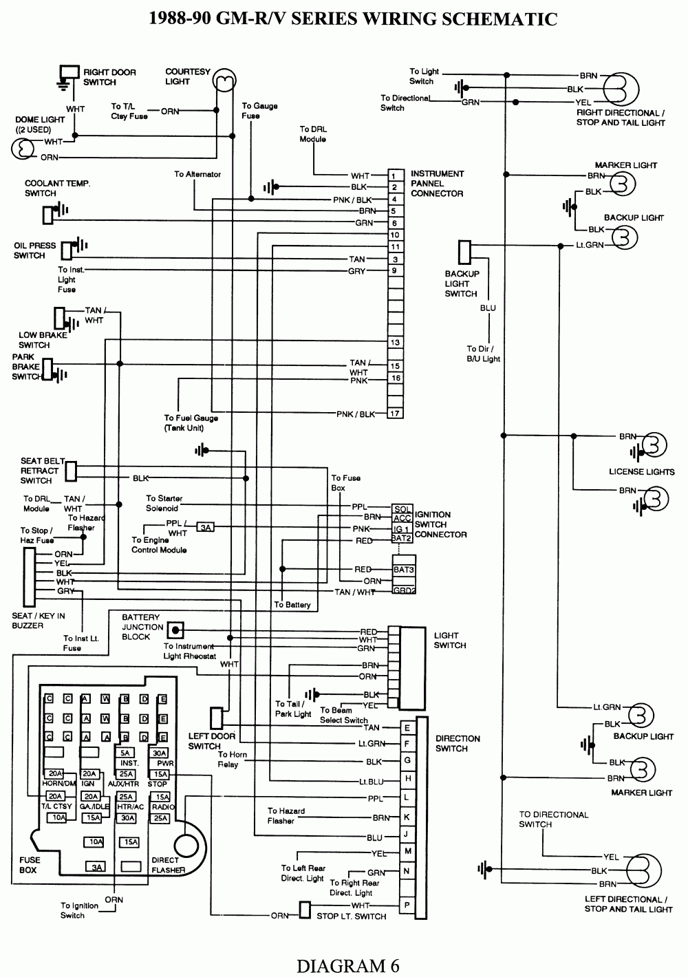
Diagram Ford Headlight Dimmer Switch Wiring Diagram Full Version Hd Quality Wiring Diagram Fishdiagrams Belleilmersion Fr
Source : pinterest.com
